Modular Optical Communication System (MOCS)
MOCS is the new modular generation of analog fibre optic based system developed by TESEO for EMC applications. The MOCS system is an innovative development of the AFOM system, which has been unrivalled in the worldwide marketplace for over ten years.
MOCS has embedded improved modularity, leverages on AFOM accumulated experience and the development of enhanced functionalities and features. Nonetheless several AFOM modules are still MOCS compatible in order to protect customers past investment.
The system overall performance and the design has been improved and optimised in order to have greater features at a cost which is less the AFOM system.
APPLICATIONS
MOCS is designed to acquire analogue signals from, and transmit analogue stimulus commands to a DUT located in an electrically hostile environment, such as the typical electromagnetic field encountered in an EMC immunity test, high voltage test areas, or wherever the electrical isolation function offered by a fibre optic cable is required.
The modular open architecture design offers the capability to address a large number of fibre optic applications, ensuring the necessary flexibility that a laboratory requires.
 A typical MOCS configuration includes:
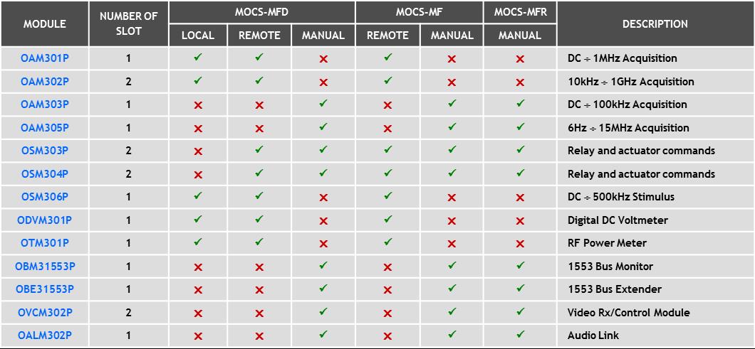
- Modular Mainframe (MOCS-MF) control unit houses one or more plug-in modules.
- There are two types of generic plug-in modules.
- An (OAM) Optical Acquisition Module receives analogue data from a DUT via an EMC shielded Optical Acquisition Satellite transceiver, and an (OSM) Optical Stimulus Module sends analogue stimulus signals to a DUT via an EMC shielded Optical Stimulus Satellite transceiver.
The acquired data and the stimulus commands are sent via FA, FB, FC type fibre optic cables. The MOCS-MF would be placed in a benign EMC area such an instrument control room, whereas the satellites would be in the electrical hostile area near the DUT.
 A plug-in module plus a satellite comprise an optical link (one or more channels, depending on the link).
The MOCS-MF can accommodate different types of links (acquisition or stimulus) to perform application specific functions. Each link type is described in a separate datasheet.
The MOCS-MF is the common component of every MOCS and is described in further detail below.
Complex applications can be accommodated by daisy chaining more than one MOCS-MF via the GPIB-RS232 bus.
 The main characteristics of the MOCS are:
- OAM and OSM satellites shielded against high E- field levels over a very broad frequency range.
- Data exchanged between satellites and plug-ins over fibre optic cables which have an intrinsic immunity to EM coupling via radiated fields.
- Can mix OAM and OSM plug-ins as well as satellites for maximum system flexibility
- The modular MOCS-MF mainframe can hold up to 12 plug-ins.
- Up to 4 MOCS-MF mainframes can be connected in daisy chain.
 MOCS-MF/MFD/MFR
MODULAR MAINFRAME
The MOCS-MF is the central unit and the heart of the any MOCS system.
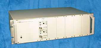
It is intended to be operated in a control room attended by the test operator and thus, it does not require electrical shielding. It can hold up to twelve plug-in modules and comes in a 19”, 3 U high, rack mountable chassis with handles.
Three different types of mainframe are available:
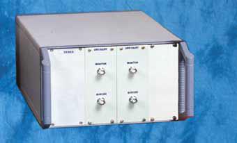
MOCS-MF 12 Channels, without display
MOCS-MFD 6 channels without display and GBIP-RS232 bus interface
MOCS-MFR 12 channels, with display
MOCS-MF DESCRIPTION
The Mainframe is connected to the AC mains and can power up to twelve plug-in modules, compared to the maximum four plug-ins of the previous system.
Power is applied via a back panel Power-on switch and an LED on the front panel confirms that the mainframe is in power-on mode.
The back panel contains GPIB-RS-232 connectors to facilitate interfacing to a personal computer as well as daisy-chaining, as needed, up to four mainframes.
A DIP switch on the back panel sets the GPIBRS232 address of the mainframe.
The RS-232 bus was selected since very little bus traffic exists between the MOCS and the PC and because it is a standard PC’s I/O equipment.
All manual controls and status indicators on the front panel of the plug-in modules can be accessed remotely via the GPIB-RS232 bus.
Another key changes since the previous systems, the computing and the intelligence has been moved from the mainframe to the plug-in modules.
Microprocessors installed in every plug-in constitute a distributed intelligence approach that dramatically enhanced the signal processing capabilities of the system.