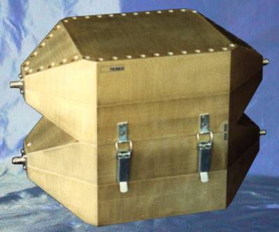
Dual TEM Cell for Shielding Effectiveness Measurements up to 1GHz
The TEM cell consists of a section of rectangular coaxial transmission line (RCTL) with two tapered sections at each ends. The taper is used as a transition to match the RCTL to standard coaxial cable characteristic impedance connectors at the two ports of the cell.
The center inner conductor, consisting of a tin metallic septum, is fixed by two dielectrical supports.
The cell is used as a broadband amplitude and phase linear transducer of RF signals into field strengths.
The field inside the cell is uniform and so it is a good approximation to simulate a plane wave in open space (far field).
Since the TEM cell operates in bi-directional mode it is assumed that two cells coupled through a common aperture may be used as a radiated field measurement system.
The coupling between cells through their common aperture yields the basic result which the dual-cell correct operation relies on.
Providing the upper side of the TEM cell with an aperture, the generated field, which is known and uniform, couples into a second similar above-standing cell.
When mounting the shielding material sample on the aperture, the coupling between the source cell and the transducing one is reduced.
The amount of this coupling reduction is a direct measure of the shielding effectiveness of the sample material under test.

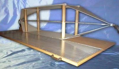
TRIPLATE01
The triplate is an OPEN TEM cell of widespread use by the automotive community. The reference specification, SAE J1113-25 of September 1995, revised in March 1999, gives the instructions on how to build and test the device.
The scope of the triplate is to radiate for a susceptibility test at high field levels a device over a broad frequency band with a power budget much smaller than that required by transmitting antennas in the anechoic chamber.
The TEM propagation is well known and controllable. The open structure of the cell avoids the reflections of the wall typical of the standard (closed) TEM cell. The size of the triplate is such that a pure TEM propagation mode cannot be extended as such at high frequencies. However with a careful initial calibration the cell can be used up to 1 GHz.
The usual rule of a DUT not higher than one third of the distance between the driven element and the outer ground planes of the triplate applies.
Therefore large objects with limited height can be accommodated, typically car on-board controllers with connecting cables. The lack of sides facilitates the access of the cables that would be difficult in a standard cell and also their routing.
Caution: the cell is of the open type and with high field levels, the field propagates also outside the cell. The cell must be used in a Faraday cage and, to prevent the field from resonating in the enclosure, the most suitable test set-up is with the triplate in a shielded room lined with absorbing material.
The high voltages and field generated in and by the triplate may be dangerous to the personnel and for safety reasons nobody should be allowed to stay in the chamber during the performance of the tests.


